Introduction
In this lab, we were supposed to calculate the volume of an aggregate pile using both Pix4DMapper and utilizing several tools within ArcDesktop. We were working within two Geodatabases in this lab, the Wolf Creek Paving and the Litchfield Mines.
The usage of volumetric analysis, based on UAS data gathered by UAVs are well used in environments that are hard to access and where it is dangerous for humans to be. People in the industry of UAS use volumetric analysis to calculate and study areas in a more cost-effective way. Surveying and total stations are not always necessary, using UAV mapping may not give the most accurate answers but often, good enough. With the spatial UAS data, it is easy to get an idea of the volumes for a specific project.
Methods
Wolf Creek Paving
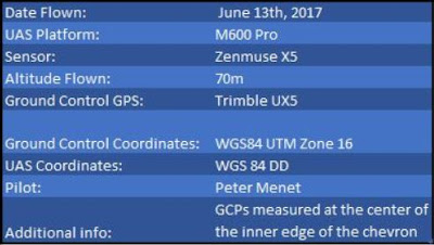 |
| Figure 1: Metadata for Wolf Creek Paving. |
I started off by generating a polygon over the piles I was interested in calculating the volumes for, which can be seen in Figure 2 and 3. This I did with the Volumetric tool in Pix4D. The red color symbolizes the volume that is above the given projected surface while green identifies what is below the projected surface. I will come back to this later but for the Wolf Paving project, 293 meters was set to be zero value (ground).
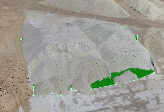 |
| Figure 2: Polygon creation in Pix4DMapper. |
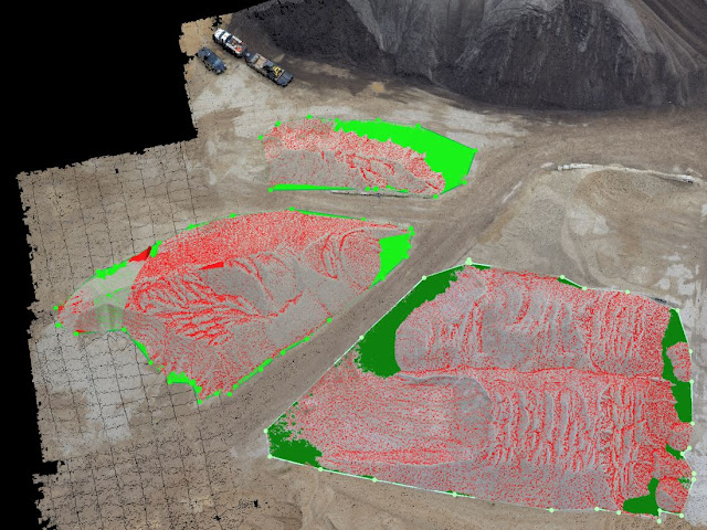 |
| Figure 3: The three piles |
Calculating was also done in the same software and these were the results. Figure 4.
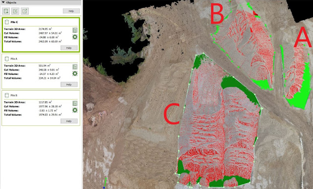 |
| Figure 4: Order of the pile and the mass calculated |
In order to see the differences between calculations between Pix4D and ArcMap, I had to do the same procedure there. ArcMap is not as easily maneuvered as Pix4D but maybe more precise. Let's see! First I had to create a new feature class for clipping a raster, but in that procedure, I had to choose the correct coordinate system like the other layers. Do it by right-click the database and choose New - Feature Class. This is easily done, but do NOT take for granted that you are in the correct system. Use the import function, as shown in Figure 5 to be sure that one uses the same coordinate system.
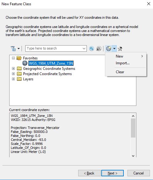 |
| Figure 5: Choose the correct coordinate system. |
I added to additional fields that could be especially important for this project. Figure 6.
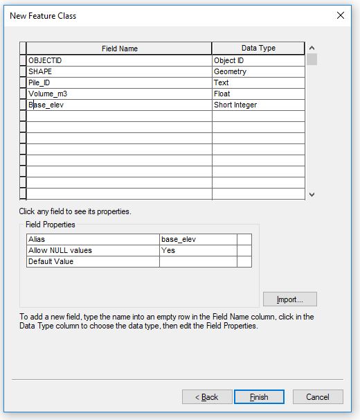 |
| Figure 6: New fields |
For Wolf Paving I created 3 polygon feature classes. After that, I was settled for creating the polygon. I had to start the editing tool and choose what Pile to draw a polygon over. Figure 7 shows, when I was in the process of drawing a polygon over Pile C, while Figure 8 displays the time when I did it for Polygon A. The three polygons will act like "masks" in the next step.
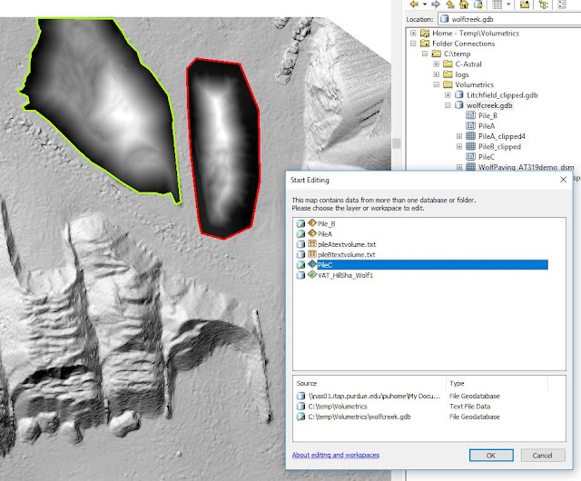 |
| Figure 7: Polygon creation |
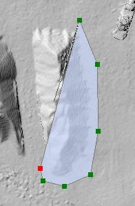 |
| Figure 8: Halfway through, a polygon creation looked like this (Polygon A) |
When finished with creating the polygons it is of utmost importance to save (!!!) the progress under the Edit tab. Or else, the next step will not be able to go through. That step was about clipping a raster with the Extract by Mask tool. That is, I clipped the aggregate piles I did volumetrics on in Pix4D. What happens here is that one uses the whole Digital Surface Model (DSM) as input raster and the polygons one just made are used for determining where the surface model to be cut. The outcome of this operation is a "clipped" DSM version of exact that area we are interested in. Figure 9 displays both a polygon before the operation is done and two that are already processed. One should make sure to leave the area outside the pile, and don't cut the pile off. This area outside will be used to find a good number to use as zero value (elevation of the surface) when using the Surface Volume Tool. I used this back and forth to generate the volume for each of the raster clips I produce.
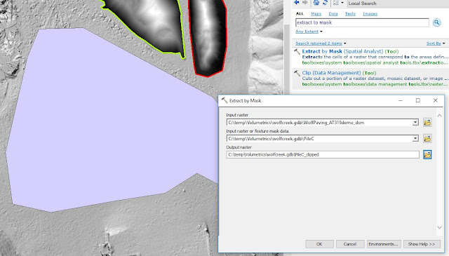 |
| Figure 9: The Extract by Mask tool |
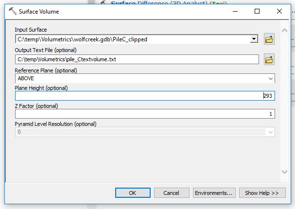
Step after this is about calculating the volumes with ArcMaps Surface Volume Tool, Figure 10. This is where one chooses the plane height (zero value) from where the volumes will start to be calculated. As mentioned earlier in this text, the ground level for Wolf Creek was about 293 meters (over the geoid). At other places that are below sea level, for instance, eg Death Valley in California, one would have to choose BELOW here. As input raster goes the clip I created with the Extract by Mask tool above.
A text file with information will be created through this operation. This can be found in the Table of Contents to the left and looks like in Figure 11.
The volume of the calculated piles is shown in Figure 12 below. In cubic meters, the volumes for the three piles I was curious about. First the result I found up top, with Pix4DMapper and below, the numbers ArcMap gave me. There are some ArcGIS exaggerations, especially for Pile C. It was the largest yes, but ArcMap exaggerates that number almost 6 times, compared to Pix4D. For pile A, it is only a "modest" doubling. I know my fellow classmates received similar so reasons for this, has to be found out on Tuesday. Dr. will have to explain.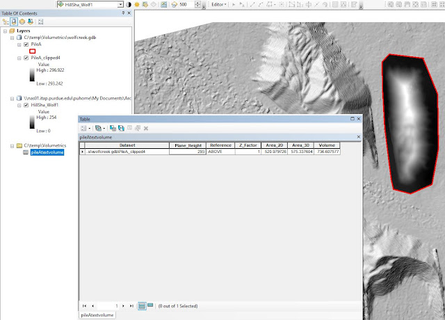 |
| Figure 11: Volumes are displayed in cubic meters. |
 |
| Figure 12: A compilation over the three piles I wanted to know the volumes for. |
The results of the work over the Wisconsin project is presented below. The map displays the three piles, which the volumetric analysis was based on.
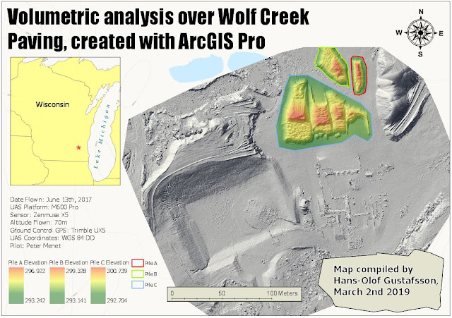 |
| Figure 13: The legend shows the elevation values, and what pile they belong to. |
Litchfield Mines
Next project. The database for the Litchfield mines had an orthomosaic and DSM from Sept 30, 2017. This geodatabase containing 3 flights from different dates, which displays how the mine alters over time. Figure 14 displays the mines at the End of the Third Quarter.
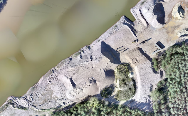 |
| Figure 14: This is how the main part of the Litchfield mines looked like at the end of September |
I engaged the Litchfield Mines about the same way as Wolf Paving site by calculating the volumetric data using three different data sets from three different dates.
As Figure 15 shows, it starts the same way by creating a new Feature Class.
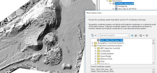 |
| Figure 15: Remember how to find the correct coordinate system? |
Below in Figure 16 is also the same principles made. This is after the Extract by Mask-tool has been used.
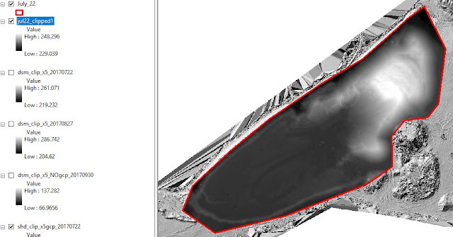 |
| Figure 16: My clip for this polygon, I did create exactly the same way I did for the Wolf Creek project above. |
Apart from the temporal aspect, where this Litchfield project got different is where one will start resampling. The method of doing this is to find the Geoprocessing Tool and search for Resample. As input goes the clipped Raster data set I just made. Checking the properties, this was on 2 cm precision level. I played some with this, which I will delve through at the end of this report, but the method for doing this is by choosing the size of each pixel. Figure 17 is a screenshot from when I generated the 5 cm layer.
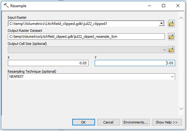 |
| Figure 17: Resampling |
After one has done the "Resample" to the new desired resolution (eg. from 2 cm start to 5 cm) one has to recalculate the volume through the Surface Volume tool. Shown in Figure 18.
 |
| Figure 18: Using the Surface tool to get a new number. |
I decided to find out the differences between 2cm, 5cm and 10cm. After I have done every step this was how my Table of Content looked, Figure 19. The initial DSM, July August, and September clips and the resampled versions of them. Also, I had the shaded clips here, but I did not create them, they came with the geodatabase.
 |
| Figure 19: My Table of Content. |
Figure 20 shows the map I created in ArcGIS Pro displays the mines site over a period from July 22nd till September 30th. These are the visuals and the discussion will be gone through in the next part.
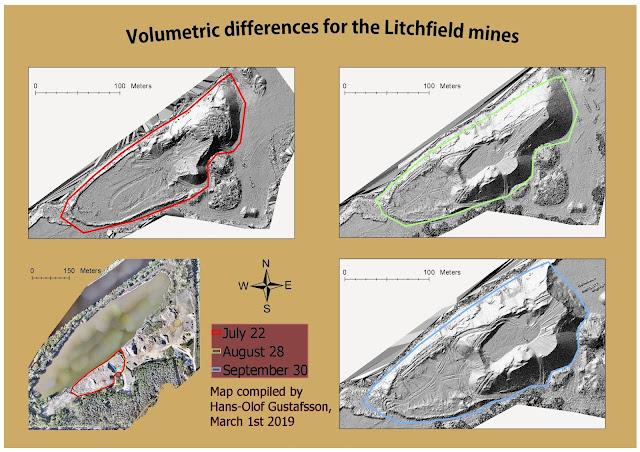 |
| Figure 20: Bottom left is a map for the whole site and how the polygons for each date alters is also being displayed. |
Discussion
There are always issues about quality and size. What quality does one actually NEED for a certain project? Well here are some tables I made for this purpose. I went deeper from what was expected and took a look at how the storage changed along with the resolution, Figure 21.
When calculating different data sets over a time span, sensors, altitudes, and spatial accuracies need to be consistent. That is the reason why I had to resample before making the volumetric analysis. This is also one of the key points to why this lab practice is important. Errors made early in the process will follow through the whole process. Consistency is important and in order to keep the UAS data trustworthy, one shall only compare apples with apples. 2 cm resolution data shall only be compared with 2 cm resolution data.
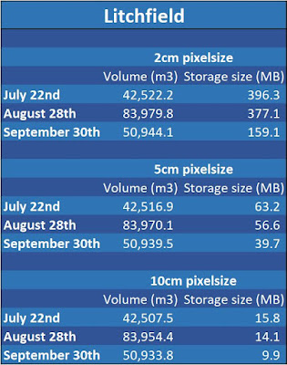 |
| Figure 21: Overwhelming changes when scaling up the pixel size. |
Figure 22 displays that starting at 2 centimeters pixel size the size of the file for July was just short of 400 MB.
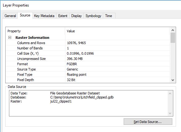 |
| Figure 22: Wow! 396 MB worth of meatloaf for 2 cm. |
Scaling up to 5 centimeters did not have any implications on the quality (which I will address further down) of the image at all, but a significant impact on the size of data, 63.2 MB. Figure 23.
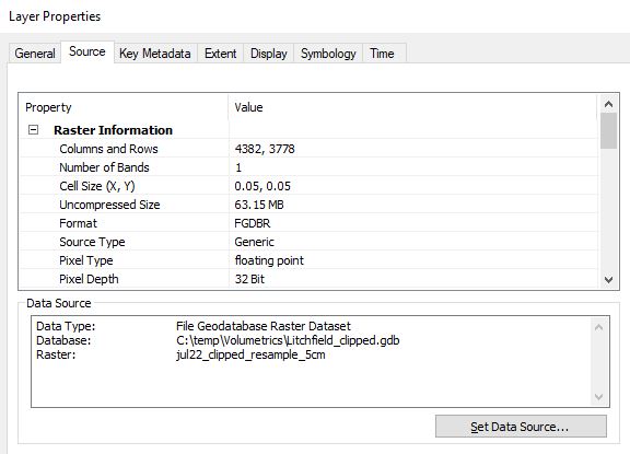 |
| Figure 23: 5 cm pixel size |
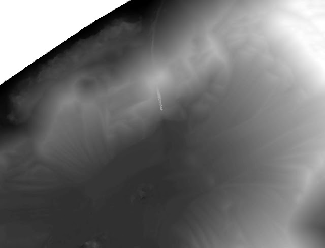
I even went down to 25 cm precision to see if I could spot a difference in quality, and I found a divergence. In Figure 24 and Figure 25 it is possible to see the difference between 2 cm and 25 cm resolution. In Figure 26 one can see the dramatic fall in storage size as well, only 2.53 MB.
 |
| Figure 24: 2 cm |
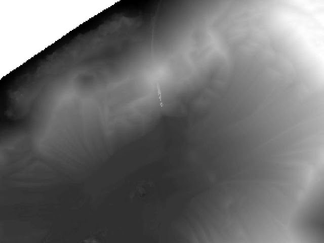 |
| Figure 25: 25 cm |
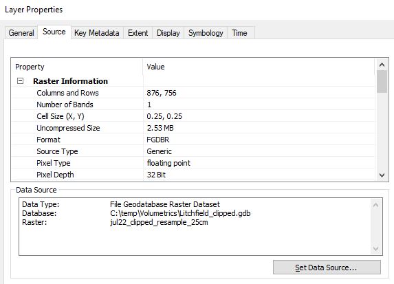 |
| Figure 26: 25 cm storage size for the whole layer is only 2.53 MB. |
Conclusion
Like mentioned above, for any project, calculating different data sets over a time period, the sensor, altitude and spatial accuracy need to be consistent. That is the reason why I had to do a so-called resampling before I made the volumetric analysis. And that is one key point to why this lab practice is important. Errors made early in the process will follow through the whole process. Consistency is important and in order to keep the UAS data trustworthy, one shall only compare apples with apples and so on. For this reason, 2 cm resolution data shall only be compared with 2 cm resolution data.
In ArcMap, I did resample the different raster data sets to new pixel sizes and produced a table over the results I found. The results shown in Figure 21 reveals it was definately (idiot-speak for "definitely") most volume covering the ground in late August. The volumes for September 30th shows that a great number of materials have been removed, which also can be seen in the images.
By reducing the quality from 2 cm pixel size to 25 cm pixel size and by that going from about 400 MB to 2.5 MB, many project managers for mines sites may choose to go for the poorer quality data sets. The second take of the results is that the actual volume does hardly change at all after the resample. The volumes for July22 with 2 cm pixel size is 42,522 m^3, while with 5 cm pixel size it was 42,517 m^3 and finally with 10 cm pixel size it was 42,508 m^3. Thus, by reducing the precision and resolution of the volumes for the whole period drops only 3 per thousand.
No comments:
Post a Comment